|
|
#61 |
|
Join Date: Mar 2012
Location: south west (uk)
Posts: 106
|
Sorry that one dragged on a bit too didn't it
|

|
|
|
#62 |
|
Join Date: Mar 2009
Location: Sardis, BC, Canada
Posts: 25,977
|
On the contrary, your pictures and descriptions are excellent. Anyone following your plan in the future will be able to get all needed answers.
__________________
Weldangrind "I figure I'm well-prepared for coping with a bike that comes from the factory with unresolved issues and that rewards the self-reliant owner." - Buccaneer |

|
|
|
#63 |
|
Join Date: Mar 2012
Location: south west (uk)
Posts: 106
|
Ron has said he'll have a read through and look at his bike when he gets a chance, he's as busy as me by the sounds of it.
Meanwhile, I've got the ECU mounted and a load of wires stuffed in my electrical box now. This sidecar is slowly looking more and more like it might even work one day! Will do some more pics later today. |

|
|
|
#64 |
|
Join Date: Jul 2009
Location: Charles Town W.V.
Posts: 849
|
Hey Jib i have my covers off . Tell me the wires you need help with and i'll have a look and see if i can get pictures .
|

|
|
|
#65 |
|
Join Date: Mar 2012
Location: south west (uk)
Posts: 106
|
Hi Ron
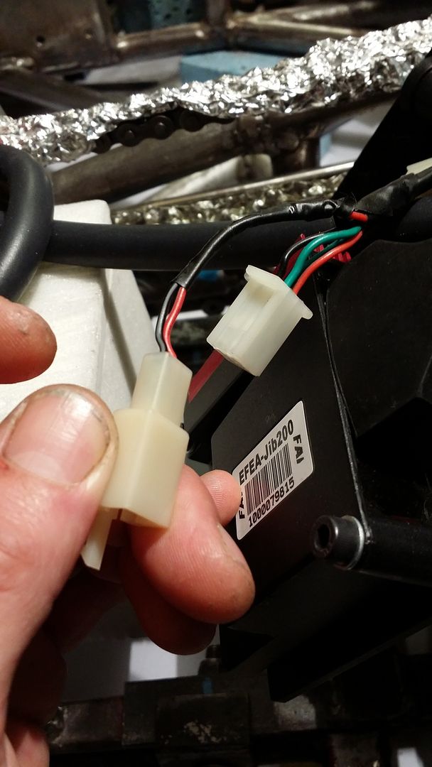
Thanks for popping in, sorry you've probably been standing there next to your bike for quite a few hours now! The main point of interest is the plug that connects the efi to the bikes power supply. It's the plug in post #55, there's a black wire which seems to be for ignition live and a red/grey wire which I'm a bit confused about. The two green being earth. I also don't have ignition as such on my bike just on off button on the bars. Maybe in should introduce something ? I also use a lanyard kill switch but this generally would stay in place all the time. |

|
|
|
#66 |
|
Join Date: Jul 2009
Location: Charles Town W.V.
Posts: 849
|
Ok Here We Go , I changed the connector on mine to suit my needs . Hopefully you can see the picture well . I see your pigtail changes wire colors ,so I am going to talk about wires colors before the pigtail . Both Green can go to chassis ground or battery negative . Black Wire Needs to go to a Keyed or switched positive power source I.E. battery power, And also. you may be able see in the picture tagged for the power side of the led /CEL . Red is only used as the negative side of the led /CEL (malfunction indicator light ) I broke the CEL that was sent to me >so just used another led , I am not sure it was necessary . But in my thoughts since the red wire goes straight back to the controller , grounding the CEL flash . I added a resister of few hundred ohms . LEDs do not need much power to work and I think keeping amp loads to the controller low reduce heat in the controller. small resister hidden in the connector .
|

|
|
|
#67 |
|
Join Date: Mar 2012
Location: south west (uk)
Posts: 106
|
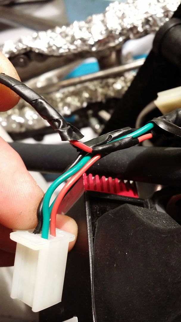
Ok thanks for that. I think what has thrown me here a bit is that my harness is slightly different for some reason. Yours looks like it's hooked up exactly like the wiring diagram I posted somewhere up there ^^^^^^ but on mine it has the same four wires terminating at the plug but in addition it has another short spur coming off with black and red/grey wires terminating at another plug, on the other side of this additional plug was the LED connected directly into the opposing side. I have now cut the LED away from the terminals and soldered a length of wire between them so I can have the LED up on the bars. The LED has a resistor in line under the heatshrink which I assume is correct.
 So these appear to be duplicate wires. I've just removed the tape and can confirm these wires are joined to the others.  So am I right in thinking I don't need to do anything with the red/grey in the main plug do you think? |

|
|
|
#68 |
|
Join Date: Jul 2009
Location: Charles Town W.V.
Posts: 849
|
(So am I right in thinking I don't need to do anything with the red/grey in the main plug do you think? ) I Would say That is correct . No need for the extra red/grey on the 4 pin connection
|

|
|
|
#69 |
|
Join Date: Mar 2012
Location: south west (uk)
Posts: 106
|
Ok thanks. That's bizarre that they should put that extra wire in!
Whilst your about I have another couple of quick ones. The tacho plug on the efi harness is just to connect up to the bikes tacho yes? In which case I don't need to use it. Coming from magneto I have blue, green, and black wires all with stripes. Still haven't had the cover off but I'm thinking the blue n green ones connect to the same colour on the efi harness and the black one is the AC feed for an AC cdi which I don't need. Sound sensible? (Although I will check in due course). The efi has a main power line with fuse, I assume this should be permanently connected to the battery or the ecu will forget what it's learnt. Lastly, are you using the fitting on the throttle body which looks like it should be a vaccum feed for something? |

|
|
|
#70 |
|
Join Date: Jul 2009
Location: Charles Town W.V.
Posts: 849
|
I'll Do the easy answers first . No need to use the tach wirews for it to run .
I am not using any vacume ports ,it's pluged off . Now the Wires from the case . Blue and green wires are needed for your timing pickup , It is AC ,But the controller converts it to DC for the CDI. I have 3 other wires from the engine case , Pink , Yellow , Black with red tracer . You'll see in the pictures Only the pink and yellow going to the voltage regulator /rectifier . 2 other wires at the voltage regulator /rectifier are green ,that will be a ground and the red will be dc voltage output i.e. 12v |

|
|
|
#71 |
|
Join Date: Mar 2012
Location: south west (uk)
Posts: 106
|
That's brilliant thanks mate. It looks like I'm on the right path then, what I've done so far is as per your set up bar the reg/rec. My old a/c zong was the same as yours with yellow and pink. The new motor has what I think is a three faze magneto and has three yellows, no pink. I got a matching reg with three yellow input wires.
So now I think I'm in a possition to finish the wiring, I just need to have a look into finding a smaller battery and know where it's going. Lastly about the main live for the ecu, is this permanently attached to the battery? I assume to maintain memory. |

|
|
|
#72 |
|
Join Date: Mar 2012
Location: south west (uk)
Posts: 106
|
Oh and thanks so much for taking the time to do those pictures
|

|
|
|
#73 | |
|
Join Date: Jul 2009
Location: Charles Town W.V.
Posts: 849
|
Quote:
Last edited by recracer; 06-28-2015 at 10:20 PM. Reason: add info |
|

|
|
|
#74 |
|
Join Date: Mar 2012
Location: south west (uk)
Posts: 106
|
Ah yes, sorry I totally missed that the live on the starter solenoid.
I'm now battery shopping!! Thanks again Ron |

|
|
|
#75 |
|
Join Date: Mar 2012
Location: south west (uk)
Posts: 106
|
Mr Yang has now said that the ECU will NOT forget stuff when completely disconnected from power which is good.
|

|
|
|

|
 |
|
|