 03-08-2019, 11:37 AM
|
#61 |

Join Date: Mar 2009
Location: Sardis, BC, Canada
Posts: 25,977
|
Interesting choice on the GM coil. What prompted that?
__________________
Weldangrind "I figure I'm well-prepared for coping with a bike that comes from the factory with unresolved issues and that rewards the self-reliant owner." - Buccaneer |

|
|
03-08-2019, 02:14 PM
|
#62 |
|
Join Date: Oct 2018
Posts: 74
|
As much as I would like to be as frugal as possible during this project, re-using the CDI and coil from the aliexpress kit seemed to be a bad decision. As I said in one of my previous posts, I wanted to give this EFI conversion every chance at success. One of my character flaws is that I get discouraged very easily. Anytime (example: now, with the wiring harness) I have to go over something I've already done and put much effort into, I get the mental thought of,
"Oh come on! I just got everything together and I was 10 minutes from starting you up, and now I have to tear you back down again and re-do what I've already done." I can foresee possible problems with the aliexpress CDI, causing me to have to tear down the wiring harness for a third time; using a possibly never-used-before-with-a-microsquirt ignition system, only having presumably one person a continent away for support with a small bit of a language barrier (he/she responds in english, but it can be a bit broken, but understandable at times), having the same person be the only source for a replacement, the CDI and coil are separate and larger in comparison to the gm coil, seeing the soldering quality in the ECU, the CDI is suspect, you get the idea. If I use the GM coil; it is widely used with the microsquirt, probably available at a local auto parts store, has lots of technical community support, the microsquirt's hardware manual lists it as a possible ignition system option and gives the pinout for the connector, the coil ignitor and ignition coil are together in one small package. TL;DR I think that the GM coil is the best bet for a reliable, replaceable, and easily diagnosed ignition system. |
|
|
|
03-18-2019, 10:17 PM
|
#63 |
|
Join Date: Oct 2018
Posts: 74
|
Update time!
Packages have arrived, items have been installed, tools used, blood sacrifices made multiple times, and sensors "talked" to the microsquirt. Ok, I'll see you in the next post. Just kidding The package from mcmaster carr came first; the aluminum sealing washers for the exhaust and a 12" length of 3/16" dia. stainless steel rod, for making the exhaust spring hooks. The exhaust washers (sounds kinda weird doesn't it? like a muffler bearing or headlight fluid) fit perfectly and I can't see how they could introduce any measurable restriction to exhaust flow. I'll be using 5 of them to get the spacing between the exhaust and the starter where I want it to be. I bought the same diameter stainless steel rod that was already welded on to the exhaust system. I figured I'd just stick with what size they use since it seems like it will be bendable with a bench vise and a hammer. I also started (haven't completed) drilling the hole in the exhaust for the o2 sensor bung. I had my doubts about the exhaust system really being stainless steel until I started to try to drill into it. I think I snapped one drill bit and dulled at least 2 more. The largest HSS twist drill bit I have is 1/2', so I incrementally drilled through the exhaust with each ascending drill bit size. I had some metal rotary rasps that I was going to use to enlarge the hole to 7/8, but they dulled almost instantly. It seems the internet's general consensus on drilling sheet stainless steel is a stepped drill bit, so that's what I ordered. The bit arrived today and I'll drill out the hole in the coming days with the bung and hook installation coming probably a week or 2 after that. Next was the package from amazon; tinned copper wire shielding sleeve, scope probes, scope probe adapters, manual vacuum pump, terminal crimp tool, 2-way connectors, 4-way connectors, 5x 10k NTC thermistors, strain gauge drivers/interface circuits, handheld oscilloscope, rs232 to TTL adapter, 50x strain gauges, and injector connectors and terminals. Yep, 90% wiring stuff. You already know what I have to do next... The copper wire sleeving is for shielding the sensor wires going into the ECU. The scope, scope probes, and probe adapters are for diagnosing electrical issues. As you can see, I am expecting at least SOME electrical issues. The manual vacuum pump is to enlarge my di-... uh... calibrate the MAP sensor to the blank tune on the ECU and to test if the vacuum-referenced mod I did on the fuel pump is working. The connectors and crimp tool are for neatening-up and weather-resisting the wiring harness. The thermistors were a bit of a last-minute addition - I have a few temperatures like oil temp and CHT I'd like to log and adding them to the bike should be easy, plus I"m always playing around with arduinos and having more temperature sensors is never a bad thing. The strain gauges and the strain gauge drivers are for an attempt at making a quick-shifter switch by measuring the strain of either the shifter arm or the shifter rod. If all goes to plan (it won't) I should be able to measure the force my foot is exerting on the shifter and at a given amount of strain, send a signal to the ECU to cut the ignition for a fraction of a second so the tranny can unload and shift into the next gear. The rs232 (serial port connector) to TTL (microcontroller-friendly voltage levels) adapter is for adding bluetooth to the ECU. The bluetooth dongle I have requires 5v MAX transmit and receive voltages, I think rs232 uses up to 24 volts (+12v for positive signal, -12v for negative signal). The adapter will allow me to pass the serial data coming from the ECU to a bluetooth dongle and allow my laptop, smartphone, or almost any other bluetooth enabled device to log data from it. The main Idea I had for the wiring harness, connectors, electric component placement, and general layout of the bike was front-to-back; more electrically noisy devices like the ignition coil, wideband controller, and the regulator/rectifier, power hungry devices like the fuel pump, and then the ECU under the seat. On the left side of the bike is the sensor/sensitive electronics and wiring side; most of the sensors are on the left side of the bike and it is always a good idea to keep electrically noisy and power-hungry devices away from sensors that use low-voltage, low-current wires to send their signal to the ECU. The right side of the bike is the power side, with the starter motor, starter solenoid, fuel pump, and ignition coil. I realize that there is only a small piece of metal between all of the sensors and the noisy/hungry devices, but given the size of this bike there isn't much more I could do. There isn't much to be said about putting the 2 and 4 way connectors on. I noted where each wire went and what it did while still using the normal connectors, cut the normal connector off, (where necessary, almost everywhere) trimmed one or both ends of the wires to be connected so there wouldn't be connectors everywhere with 12" tails on them, crimped the new terminals on, and installed the terminals in the connectors. In one of the pictures, you can see a detail shot on a star-ground point I made and am using. Everything minus the stator and the ECU sensors ground to that point. Hopefully this will eliminate or at least reduce voltage differentials between the ECU and anything else. The wires that came soldered to the crank position coil (VR sensor) weren't shielded in any way. I wanted to make sure that those wires were shielded as much as possible from the sensor to the ECU. The copper sleeving wouldn't stretch enough to fit the connectors in, so I had to leave that part unshielded. I removed the factory wires from the VR sensor and soldered in the shielded wires that came with the microsquirt ECU, you can see a shot of the VR sensor in the pics. The kill switch, as it was, would kill the engine by grounding out one of the leads coming from the VR sensor. This isn't really the "correct" way to stop and engine while keeping the ECU on. The more common method is to disconnect power from the ignition coil. To disconnect power from the ignition coil, I would need the kill switch to be normally closed (when in the run position, the wires coming from the kill switch will be connected; when in the stop position, the wires will be disconnected), but since the bike originally stopped the engine by switching a wire to ground, that means that the kill switch was normally open (run position = wires not connected, stop position = connected). I was very fortunate and happy after I opened up the right control cluster to see that there were 3 points for wires to connect to on the kill switch. One was common, one was normally open, and one was normally closed. From the factory the wires were connected to the normally open and the common points. I just switch one wire from normally open to normally closed. Now I have a kill switch that will stop the engine and keep the ECU on. In the last pic you can see some of the progress, from top to bottom, of the wiring harness being made. |
|
|
|
03-22-2019, 11:49 PM
|
#64 |
|
Join Date: Oct 2018
Posts: 74
|
Smallish update today.
Since I had already wired up the bluetooth module I have for the aliexpress ECU, and I'm now using the microsquirt, I had to undo part of the wiring I had done. The connector that the aliexpress ECU used for tx/rx data had four wires going into it; switched +12v, tx, rx, ground. The microsquirt only has tx, rx, and ground so I had to source switched power from somewhere else. I decided to tap into the switched power wire that controls the lighting and dashboard. I ran the wire from where I tapped into the wiring harness along with a ground wire to just behind the ECU under the seat with some leftover length just in case. Now, I didn't want to just bundle up the bluetooth module, the voltage regulator, and the rs232-ttl adapter in a ball of electrical tape; I have been trying throughout this project to do things better than I would normally, and try and make things look... better. Not good, just not a, well, a ball of electrical tape. It turns out that the case that the aliexpress ECU came in would perfectly house all 3 modules and still be able to close. One of the pics shows how I laid out the modules and another shows the case back together with hot glue doing its best to seal it. It turns out that the spot that I wanted to mount the, lets call it a BT case, right behind the ECU wouldn't work, the seat would come down and press on it. I decided to mount it to the inside of what I am calling the bike's left side quarter panel. It's the black plastic fairing piece with a wire mesh "vent hole" that's above the rearsets. The wires for the power would still reach, thanks to the little bit of extra length I gave myself. Thanks, past self! The serial cable for the ECU is probably 4 or 6 feet long; more than enough to mount the BT case anywhere on the bike. I opted for the good ol' faithful zip ties to mount the case to the fairing. One of the things I had to redo since I switched ECUs is re-sync the ECU timing to the engine's timing; essentially making sure that the engine is at a given timing degree when the ECU thinks it is. I had trouble getting my timing light to flash on every spark. When the engine was turning over at a constant speed, the timing light would only flash about once every 2-5 sparks. I took the spark plug out and grounded it against the engine case and tried cranking the engine again. I noticed the first 2-3 sparks right after starting to turn the engine over were big, bright, blue-purple sparks and then only once every about every 5 sparks. Between the big sparks were tiny little pissant sparks that I'm guessing weren't enough to trigger the timing light to flash. I am still using the battery that came with the bike from china, and all the attempts at turning the engine over to get the timing correct had dragged the voltage down to near 11.9v (charged 12v lead acid batteries are usually ~12.6v) . Time to put the battery on the charger and go solve another issue somewhere. A few hours later, with the battery at ~13 volts, fresh off the charger, I tested the timing light and the whole ignition system using the tuning software's ignition/injector test mode to eliminate any cranking-related problems. This mode lets me fire the spark plug with a given dwell time, at a given RPM-emulating speed manually. It appears that the low battery was at least contributing to the weak spark, because I got every time big, bright, audible sparks. I hooked up the timing light to test it again, but the usual mild hum that normally comes from it when the trigger is pulled was absent. Jiggling the power leads didn't help any, so I cracked it open and spotted what looked like a place where two insulated wires were touching and had probably shorted together. I replaced one of them, the other seemed good enough to continue to use. That fixed it right up. Bright flashes from the spark plug and the timing light! The blueish-purple wire in the pic was the one that I put in as a replacement. One thing that had come to my attention when I was re-soldering the kill switch is that since I had to re-wire the kill switch, the tachometer in the dashboard would no longer receive a signal because the kill switch and the tach used the output of the non-grounded wire from the trigger coil. The trigger coil/VR sensor is now directly wired to the ECU and I'm not going to compromise the integrity of the signal by splitting it to other devices. Luckily the microsquirt has an output just for such an occasion. I can designate one of four spare outputs to give a dashboard-friendly tach signal. It would have been rather odd to just take pics of the dashboard with various RPMs displayed on it, so I shot a video showing a few different test frequencies sent to the dashboard. One of the other outputs I am going to use as a warning light for either the cylinder head temp, overall cylinder temp (where the engine temperature sensor is bolted to the engine in my previous posts), or oil temp. Another I might use as a warm-up indicator - if the ECU is feeding the engine extra fuel because the engine is still not up to operating temperature, this light will be on. The possibilities for setting(s) what will cause an output to turn on/off and under what condition(s) are nearly limitless. That's about it for now. In the coming few days, I will try and take the exhaust to get drilled (the step bit I bought didn't work out) and welded. I cut the SS rod I bought from mcmaster carr into short pieces and bent them into hook shapes with a bench vise and a hammer. If the shop I go to isn't able to drill out the hole in the exhaust to the size I need, there's no way around it, I'll need to buy a drill press and a GOOD ($50+) cobalt-containing drill bit, be it twist, step or otherwise. |
|
|
|
03-25-2019, 11:47 PM
|
#65 |
|
Join Date: Oct 2018
Posts: 74
|
The unusual sparking issue has persisted so I went and asked on the megasquirt forum what could be causing it and/or if I didn't have the settings right in the tuning program. Turns out in the case of the zs190 engine, the ECU needs to think that it is controlling a parallel twin engine. The ECU, as it is configured, thinks the signal from the crank VR sensor is coming from the cam/distributor (spinning half the speed of the crank), so it thinks the engine is spinning twice as fast as it really is. The ECU needs an RPM input signal once per 720 degrees (4 up/down strokes) on a single cylinder engine. I can tell the ECU that the engine is a parallel twin (which would need a RPM input signal once every 360 degrees, which is what the 190 does) and just ignore the spark output for the second cylinder; that way I'll be running wasted spark on just one cylinder. It does seem like a bit of a work-around, but my particular use case is probably very rare for these ECUs, they are mostly for 4+ cylinder engines. I have yet to test and confirm what I've been told to do on the megasquirt forum, but I'm positive they won't mislead me.
I noticed from the first day I had this bike that on the LCD dashboard there was a section that was there, but not being used with the abbreviation "TEMP". It's to the right of the word "total" and above the odometer numbers. Curiosity got the better of me and I took the dash off the bike and took it apart as much as I could. luckily there was some silk-screen labeling next to the main connector that seemed to match what wires went to those connectors. I didn't write down all of the wire <-> PCB connections, most of the important ones are clear like power, ground, ignition, neutral, right turn, left turn, high-beam. There were also 6 pins, all together in a line, labeled oddly enough 1-6. Thats where the stock engine's gear indicators went. But... there's 6! Assuming you have an engine up to 6 speeds that has gear indicator outputs for each gear, this dash will display your current gear. Of course, this does me no good, all I have is a neutral indicator. Oh well. I tried probing around the two unused connector pins, but got no reaction from the dash. I did, however, discover two more... enticing things about this dash. First, above and to the right of the neutral light and above and to the left of the high-beam light, there are two more indicator light "channels" WITH an LED for both of them already soldered on the PCB! There are also icons (a thermometer for temperature and a generic check-engine-light) already engraved in the black plastic piece that covers the dash. So, theoretically, even though I haven't been able to get one of those LEDs to light by probing the main connector, I could just drive one of those LEDs with an output from the microsquirt directly (with a resistor). One problem with that is that I would have do de-solder all of the LCD connector pins to be able to get to the side of the PCB where the LEDs are mounted. I don't think I can do that. The second thing I discovered is how to change some parameters on the dashboard. I don't know what the parameters are for and I don't know what I would be changing them to, but I can (won't though) change them. With your bike off, press and hold the "CLR" button while turning on the ignition. Something like what I have taken a pic of should be displayed. I THINK that one of these numbers is a calibration for the speedo. I'm not positive what the other number(s) are. I'll look into it. A few more parts and services; non-chinese fuel lines all-around, tap and die for the most common bolt thread pattern on Chinese scooters/bikes - M6x1, and I finally got the exhaust bung and hooks welded on. It could look better, but it appears to be air-tight and that is what matters. I had them drill out the hole for the bung, that saved me from having to buy a drill press and a very expensive bit. Ironically, I also bought a drill press. I decided that paying the price of a drill press to not have to hurt myself trying to hold a drill straight AND press it into the work was worthwhile. I know I've said this before and I'm gonna jinx myself even thinking this, but there is very little left to do;
|
|
|
|
03-26-2019, 08:23 AM
|
#66 |
|
Moderator

Join Date: Oct 2016
Location: Houma, La.
Posts: 11,549
|
 Excellent documentation of the process. I've read through this thread a few times. Excellent documentation of the process. I've read through this thread a few times.
__________________
2023 Lifan Lycan 250 Chopper 2023 Venom Evader 2022 Lifan KPX250 2020 Kawasaki Vulcan S 2004 Honda ST 1300 2016 Black Hawk 250 (sold) Keihin PE30 carb,125 main,38 slow.Pod filter,ported & decked head 10:1 CR,Direct Ignition Coil,15/40Sprockets,NGK DPR8EIX-9,De-Cat,Dual Oil Cooler,Digital Cluster 2016 Cazador180 XL 2014 Coolster150 JerryHawk250.com My YouTube Channel |
|
|
|
03-26-2019, 12:03 PM
|
#68 | ||
|
Join Date: Oct 2018
Posts: 74
|
Quote:
Quote:
While were talkling about dashboards, I found out what all or at least most of the pins on the main dashboard connector do. I take no credit for discovering this information, I just found what others have posted on the internet. From what appears to be a Japanese person's project blog, I found this picture: 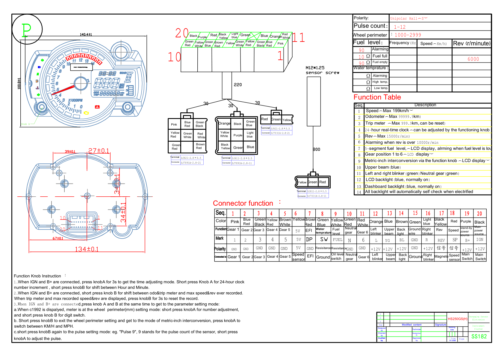 showing the pinouts from a similar universal type dashboard and most of the silk screen labels match. I also discovered another kind soul that took pictures of the instruction manual that comes with the grom-style dashboards. On this product page a reviewer posted the manual that is shipped with a universal dash. It describes how to get into the settings menu (the same as what I described in my previous post) and more crucially, what those numbers mean. I couldn't figure out how to directly download the images posted from the reviewer, so I took screen shots and I'll attack them to this post. Again, I take no credit for taking these pictures, I am just re-posting them here in case that amazon product page goes 404. The images are very small and grainy, so I'll try and transcribe the important bits. The first set of three numbers in the configuration menu (after you press and hold the CLR button and power on the ignition) is the circumference of the front wheel divided by the number of magnets used for the vehicle speed hall effect sensor. I REALLY don't know how I was getting a nearly correct speed reading with that set at 021. Someone else who reviewed the dash said, "...I have a 21in front wheel, started with a setting of 005 and worked up to 008 and that setting seems to be the closest to the GPS speed..." So perhaps some trial an error is needed to get a good, accurate speed reading. The second set of two numbers is setting the resistance for the "oil level" (I think they mean fuel level) and the number of ignition events/engine cycle. The first number is the resistance for the fuel level sensor. The manual says 1 represents 100R (100 ohms) and 5 represents 500R (500 ohms). I just measured the resistance of the fuel level sensor in my tank and when empty, it reads 100 ohms +/- 2 ohms; full it reads 10 ohms +/- 2 ohms. That matches the number "1" in the pic I took of my dashboard settings. The second number is the tachometer setting. "2" is for single cylinder engines and "4" is for 2 or 4 cylinder engines. Again, this matches what was shown on my dash. It appears that this dash is quite suitable for a range of bikes. I suppose that isn't very surprising considering Chinese manufacturers are very good at re-using existing parts in new designs. |
||
|
|
|
03-26-2019, 08:40 PM
|
#69 |
Join Date: May 2015
Location: Houston area
Posts: 1,902
|
Phenomenal thread. I wish the 190 engine had been available when I still had the Honda S90.
I would definitely stick with a good old carb.
__________________
"Its not WHAT you ride; its THAT you ride" |
|
|
|
03-27-2019, 08:40 AM
|
#70 | |
|
Moderator
Join Date: Oct 2016
Location: Houma, La.
Posts: 11,549
|
Quote:
To much info here to get buried in the forum.
__________________
2023 Lifan Lycan 250 Chopper 2023 Venom Evader 2022 Lifan KPX250 2020 Kawasaki Vulcan S 2004 Honda ST 1300 2016 Black Hawk 250 (sold) Keihin PE30 carb,125 main,38 slow.Pod filter,ported & decked head 10:1 CR,Direct Ignition Coil,15/40Sprockets,NGK DPR8EIX-9,De-Cat,Dual Oil Cooler,Digital Cluster 2016 Cazador180 XL 2014 Coolster150 JerryHawk250.com My YouTube Channel |
|
|
|
|
03-27-2019, 11:18 PM
|
#71 | ||
|
Join Date: Oct 2018
Posts: 74
|
Quote:
After that, my future project was set in stone. Quote:
Ah shucks, my first stickied thread. All of you are going to make me blush  . In all seriousness, thanks dude, I really appreciate that. . In all seriousness, thanks dude, I really appreciate that.I got to trying the new 2-cylinder settings today. There are a few combinations of settings in the ECU that could give me the amount of fuel and number of sparks I need. For now I'm settling on "2" cylinders, one injector, wasted spark, one injection per engine cycle, engine and injector size stay the same. From my understanding, these settings will tell the ECU that there is a single injector shared between two cylinders in a parallel-twin configuration. Spark is shared between the "two" cylinders; when one cylinder is on it's compression stroke, the other would be on it's exhaust stroke, so the spark can happen on both cylinders at the same time. We only have one "real" cylinder, but the spark output from the ECU will still work. In the real world, on the bike, the electrical gremlin was still there with the new settings. I had also noticed that the tachometer signal was wildly jumping around. There was a setting in the ECU to filter out rogue crank speed signals. I can choose one or a combination of noise rejection settings based on the width of the tach pulse, dead time after tach pulse received, and time between pulses. I started with using the width-based rejection and after a bit of tuning, I have it almost acceptable. Within a few days, I'll try using the time-between-pulses (they call it tach period rejection) setting with and without the width-based filter. I have been giving thought to staring out with going fuel-only ECU control during the first part of the tuning adventure. Unless I had a really lean mixture, I have never had a scooter/motorcycle CDI cause knock. The spark advance map I have now is a copy of what was sent on the aliexpress ECU. I have no idea if it is good, let alone safe. If I use the CDI and CDI coil, I only have to worry about a lean mixture blowing up my engine, not over-zealous ignition advance. Luckily I had the foreskin... I mean forethought to keep the crank VR sensor usable by a CDI and kept the stock CDI connector wired into the harness as well as the CDI coil's power feed and ground wires. I haven't yet made the final decision to use the CDI or not, but as long as I can send the crank VR sensor's signal to BOTH the CDI and the ECU with little to no signal degradation, I will be leaning toward the CDI. Back to the dashboard. I used the pinout diagram I showed previously and mapped functions to all of the pins on the dash's main connector. The only differences in the PCB labeling was; the +5v to the front wheel speed sensor is marked "H+" on the dash, not "5V", the check-engine-light was labeled "F", not "DP", the fuel level input was labeled "EF", not "FUEL", and the tach signal was labeled "ZS", not "REV". Nearly all of the wire colors are different along with the pin positions in the connector, but ALL of the connections were there! The main connector the dash uses is almost universally used as a power connector for motherboards. Google "ATX 20 pin connector" and you'll see billions of results. I happen to be a hoarder of extra/surplus wire, as well as all things electro-mechanical. I had on old power cable from a modular power supply. I extracted two wires with terminals from the cable and plugged the terminals into the two vacant spaces in the dash's connector. Now I had easy access to those inputs while the dash could be fully connected to the bike. I love when stuff like that just falls into place. On one of the pictures I posted before from an amazon reviewer had resistance vs degrees points for the temperature input pin. It looked like the resistance went from about 80 ohms (120 degrees C), up to about 500 ohms (60 degrees C). I got a 1000 ohm potentiometer and connected it between the dash's temp input and ground. I didn't hook up a multimeter to see what was happening at what resistance, sorry. If I turned the pot all the way to one side (less resistance), the temperature indicator eventually turned on. If I turned the pot all the way to the other side, eventually the indicator light would go out. If I turned the pot to the middle, and then clicked through the display modes on the dash (odometer/trip), a temperature would display on the dash! To avoid confusion and increase compatibility, the dash will just not give you the option to view the temperature if it thinks that either nothing is connected to the temp input, but it will turn on/off the temp indicator without the temp display if you connect the temp input straight to ground. I heavily suspect there is some hardware or software smoothing of the temperature signal. I measured a 14 second delay between grounding the temp input and the indicator light coming on, and a 8 second delay when letting the temp input float (not connected to anything). Not exactly a basic on/off light, bit still perfectly usable as a indicator. Also, the temperature display on the dash goes from 0 degrees C to 71 degrees C. At >= 46 degrees C, the displayed temp starts to flash, and the indicator light turns on steady. At 71 degrees C, the temperature stopped rising as I was still turning the pot, and eventually the temp display went an odometer, but the temp indicator light stayed on. The input for the CEL is just a basic light connection. Just ground the CEL wire from the dash and the indicator turns on instantly and turns off instantly when left floating. Both the temp and CEL light are red, though the CEL looks orange in the pics. With the dash on the bike and connected to the wiring harness, all the indicator lights still worked and the temp display could be summoned if needed. Looks like we have two more free indicator lights. Almost. The clear acrylic that covers the dash has a black plastic backing piece glued to it that is blocking us from seeing the two "new" lights. I don't think I could drill precisely enough to only go though the black plastic and not the clear. Unless I think of a better way, the current kinda-planish-thing is to just drill straight through the back and clear plastic, get some CLEAR silicone/silicone alternative/epoxy/glue/resin, and fill the new light's holes up to the thickness of the arcylic piece (guesstimate ~ 1.5mm). Although I don't intend to ride in rainy weather or to store this bike out of a garage, keeping the dash as water/weather resistant as possible is something I want to do. I think that is it for tonight. |
||
|
|
|
03-29-2019, 09:59 AM
|
#72 |
|
Join Date: Mar 2018
Posts: 249
|
Your factory dash looks a bit different than mine. I think the Ice Bear Fuerza has a dash that is closer to the Grom's.
Here's the wiring for mine. Not sure if this helps or would be useful info for you. http://www.chinariders.net/showthread.php?t=21374 I'd like to swap to that Trailtech. Looks really nice. 
|
|
|
|
03-29-2019, 02:23 PM
|
#73 |
|
Join Date: Oct 2018
Posts: 74
|
Yeah, it looks like the icebear's dash is more of a copy of the grom's dash, whereas mine is I guess "inspired" by the grom.
From a cursory glance at the colors and pinout, it appears that both of our dashboards are compatible with each other; they use the same color wires for functions and might even have the same LCD, just in a different case. Even though I don't immediately need the information you posted, I am always ravenously eager to learn and discover new information. I might be a computer. I just got done painting the small metal pieces for the license plate holder and the muffler support as well as making the two hidden indicator lights in the dash visible while riding. It isn't pretty, but it works. I'll do a full-length post within the next few days showing what I did. Yesterday the high temperature outside was around 66. Darn you mother nature, taunt me no longer! |
|
|
|
03-31-2019, 12:43 AM
|
#74 |
|
Join Date: Oct 2018
Posts: 74
|
Taking a break from stuff like a rats nest of a wiring harness and settings like crank trigger offset angle to doing something comparatively mindless like painting is a welcome reprieve. I took all of the angle brackets I used for the license plate holder and the exhaust hanger bracket outside (it happened to be a warmer-than-average day), ground them down to bare metal and primed, sealed, painted, and attempted to clear-coat. All of the paint I am using is left over from previous projects, and all of the cans were at least half-empty. I had enough primer and primer-sealer and EXACTLY enough black paint, but just a few spits of clear coat. I don't think any of these pieces will see any real abrasion except from being bolted/unbolted, so no real worry there.
Next I tackled getting the two holes drilled in the dash for the two newly found indicator lights. What a perfect job for a drill press! The previous day, I traced the outline of the white plastic light guide piece of the dash with all the indicator light holes. I then taped the outline to the front of the dash and lined it up as best I could. The drill worked as it should and gave me two very straight, smooth-ish holes where I needed them. I wanted to keep the dash as water/weather-resistant as possible, so I needed to seal up the holes I just drilled with something that would let light pass through it. I would have liked silicone, but 1. it is too viscous to settle into having a flat surface and 2. it isn't completely clear, it's more like trying to look through a few mm of milk. I settled on epoxy; it flows well enough to have a smooth-enough surface and dried clear (but with lots of tiny bubbles). I put a piece of scotch tape over the top of the drilled holes on the front of the dash to keep the epoxy from leaking out, then flipped the dash over and filled each drilled hole to the point where the surface of the epoxy was flush with the plastic of the dash, and let it set for a day. You can clearly see the indicator light's color, although the "icons" in the dash are distorted. That doesn't really matter to me, I use the color and location of the lights for recognition; red light on the right side of the dash? temperature. Red light on the left side of the dash? engine is still warming up (or whatever condition I set for that light). I attempted to make a engine block temperature sensor using one of the 10k thermistor and a ring terminal crimp (pictured). It did not work. I did successfully solder the ring terminal to the temp probe, but the probe short-circuited internally when I tested it afterward. I made another one that I jb-welded on. I'll let you know how it works once it dries. I was trying to use the 10k thermistor instead of the 100k one that came with the aliexpress kit because when using the 100k one, the difference to the ECU between 60F and 100F is only 0.127 volts .With the 10k thermistor, the difference between 60F and 100F is 0.757 volts; greater resolution in the range we need it. The ECU can detect (I'm kinda guessing on the exact numbers) 0.005 volts change on the temperature input; each 0.005 v is one "step" of resolution. If there is only 0.127 volts between the numbers we gave earlier, the ECU only has 25 steps of resolution, or a resolution of (100-60)/25 = 1.6 degrees F per step. Whereas with the 10k thermistor, using the same 0.005 v step and 60-100 range, the ECU has 155 steps of resolution or 0.25 degrees F per step. I'm still going to try and use the GM temperature sensors; they are much more robust than the quite-flimsy thermistors, but they are also MUCH bigger. I was intending to put one of the thermistors in the air filter to measure the IAT (intake air temperature), but there is just no way one of the GM temp sensors would work there. I asked on the megasquirt forum about remotely mounting the IAT sensor since I have essentially NO intake plenum or piping to speak of, it is literally air filter -> throttle body. I was told that remote mounting of the IAT sensor would work in my case (no under-hood area to trap heat and increase charge temperature; IAT essentially always equals ambient temp). The place I have ear-marked for the IAT sensor is around about where I put the CDI when I had the aliexpress ECU installed. It shouldn't get heat soaked from the engine back there, and it will get some airflow over it when riding at speed. As for the engine/coolant temp sensor, I have three possible places in mind: 1. The same location the 100k thermistor is bolted to (look at my previous posts to see where I installed it). Problems with this location are I would have to drill out the threaded hole in the cylinder to a larger size to fit the tip of the temp sensor in, and then I would have to hold and secure the sensor there somehow. I really don't want to jb-weld anything to the engine. I could also make a ring terminal fit the sensor's tip and NOT SOLDER, but epoxy or jb-weld it on there. I would still have to secure it in place somehow; the sensor is too heavy to be left secured at only one point, especially on something as violently shaky as an engine. Pros are easy to access and replace, and reading the temperature of the cylinder, not the oil. 2. The oil channel access bolt next to the position mentioned in place 1. Problems with this location are having to thermally connect the temp sensor to the bolt, having to thread the tip of the temp sensor (I don't even know if there is enough meat on the tip of the sensor to be safely threaded), or having to find and buy multiple pipe thread adapters to go from the threads on the engine block to 3/8 NPT on the sensor, while having enough clearance for the tip of the sensor. Pros are easy (though not quick) access and replacement. 3. The spark plug hole. Make a CHT sensor with a ring terminal and put it between the cylinder and the spark plug. Problems with this location are, again lots o' vibration, having to jb-weld a ring terminal to a sensor, rendering it useless in any other situation, and lots of airflow over the sensor body while riding at speed, possibly cooling it below the temperature of the cylinder head. Pros are this would probably be the most accurate reading of the temperature we want, it can aid in tuning, and easy (though not quick) access and replacement. I'm really not sure which location I'm gonna go with. Maybe a slight lean toward the current temp sensor location. There were quite a few wires left over, unused coming from the ECU. Since I installed it (the ECU), I had a plan to wrap the unused wires together in a circle and tuck them behind the ECU. I tried to do this once by just stuffing the wires into the plastic wire loom sleeve in a circle, but that didn't work well. I had straighted the wires and tape them together about every 6-8 inches, then wound them on top on one another and taped them to each other, then finally putting the plastic sleeve over them. I seat does slightly press on the sleeve when installed and with a person sitting on it, but no where near enough to damage the wires inside. I have been (and still am) wondering if the 125's and the 190's CDI is DC or AC. I can easily see that the 125's CDI got its power from the black switched +12v wire, but it is also comparatively smaller than most DC CDIs I have seen (from what I have read, DC CDIs need to be bigger because they need room for additional circuitry). It is only 1mm smaller than the 190's CDI. The 125's CDI has four wires/pins; trigger, ground, power, and output to coil. The 190's CDI only has one more ground pin. The wiring harness that came with the 190 would have the CDI getting AC power, and the 190 stator has a high voltage winding, the 125's stator (pictured) does not. At this point, since the 125 stator didn't have any HV windings, I am relatively certain the 125's CDI is DC (or at least works with DC). The 190's CDI... the wiring harness connections point to AC, but being the same size as the 125's CDI points to DC. I guess I'll have to try the 190 CDI on DC first (DC first because I am guessing that feeding 12 volts into something that usually needs 100+ won't hurt it, but doing the opposite will make the magic smoke escape). If it doesn't work on DC, then its on to AC. If that doesn't work, then I screwed something up. I think I broke my cat. Last edited by glavey; 03-31-2019 at 11:23 AM. |
|
|
|
04-03-2019, 11:30 PM
|
#75 |
|
Join Date: Oct 2018
Posts: 74
|
We're getting close dudes and dudettes, we're getting close.
I got the gm map sensor installed without much trouble. One thing I did have to do was cut out key ways in the map sensor connector (pictured). As odd as it may be, it was cheaper to buy a clearly knock-off sensor + connector rather than just buying a connector. I bought the cheap senor/connector just for the connector, but it turns out there are different connectors for different sensors; mainly for 1 bar, 2 bar, and 3 bar sensors. The cheap sensor was a "3 bar" sensor and so was the connector. The genuine GM sensor was a 1 bar sensor. Nothing an xacto knife can't fix. The "genuine gm" map sensor I bought did come in a acdelco box, but not the usual kind with the hologram on it. Either this is just an old-stock part and box, or the overseas sellers are getting more crafty at selling counterfeit parts. I have tested the sensor, and it does work and read as it should, so no worries thus far. I attempted to make a holder/adapter for one of the gm temperature sensors, but failed miserably. I had a short piece of very thick gauge wire with two copper crimps on either side. I cut off the wire from the crimps and pounded the remaining bits of wire with a hammer and a punch in a vise. Then, I TRIED to re-open the two "jaws" that held the wire in place, but the copper was too work-hardened from being crimped, and I just mangled the whole thing. Oh well, I tried. The temperature probe I jb welded on to a ring terminal worked out very well, and until I find a good way to mount the gm sensor somewhere to the engine, I'll be using it as the engine temperature sensor. I also bought 5' of 3/16 and 5/16 fuel hose to use for all the low-pressure fuel runs, along with a fire extinguisher, gasoline-resistant sealant, various ratings of fuses, a bar clamp phone holder, and a 5/16 quick connect to 5/16 hose barb adapter. The fuel hoses are self-explanatory; I don't have an anti-gravity pump so I have to use hoses to move fuel to and from the gas tank. The fire extinguisher is, I hope, even more self-explanatory. I want this engine to remain an INTERNAL combustion engine. The fuel-resistant sealant is because when I took the fuel level sender off of the tank, I noticed that the rubber sealing washer was put in incorrectly and pinched (pictured). I don't know if that will cause a leak, but I am going the safe route and adding sealant. Fuses; so I only have the good kind of sparks. The phone holder is so I can connect the microsquirt to an app on android that gives me a choice of a few dashboards with most pertinent information easily read while I am riding. Don't worry, I have an old pre-dropped phone I am going to use for the dash display. The quick connect to hose barb is for connecting to the high-pressure side of the fuel pump. I mentioned in a previous post that the outlet on the fuel pump is supposed to be used with quick connect fittings, not with bare hose. The adapter is the necessary piece to go from the fuel pump to the high-pressure fuel hose. Note that they are called quick CONNECTS, not disconnects. You either need a special tool to disconnect these, or do what I did and buy one with a button you can press to release the adapter. I was going to use the existing barb on the top of the fuel tank for the fuel return, but I just couldn't stop thinking that since the fuel hose going to the pump from the tank and from the pump back to the tank are the same size, if there were even a little bit of flow restriction on the return hose or the fittings, the fuel wouldn't be able to go back to the tank fast enough and cause higher-than-intended pressure on the high-side of the pump. Using a larger size hose along with larger fittings on the return route gives lots of room for high-flowing fuel. I chose a location on the tank that wouldn't be too far from the pump and not interfere with the plastic tank fairings. Mostly because of the inability to reach any other place in the tank, I chose to drill a hole near the rear of the tank, about an inch above where the tank fairing ends. Drilling the hole went without problem. I used a 1/8 npt female-female coupling, 1/8 npt male close nipple (yes, that is the correct term), a female-female 1/8 npt 90 degree elbow, and a 1/8 npt male to 5/16 hose barb adapter to make a clamping bulkhead fitting that hopefully along with jb weld will make for a leak-proof fuel tank return connection. I had to sand some of the paint off the tank to get a good bond with the jb weld. I ran out of black paint when I painted the license plate and exhaust brackets, so I had to use white touch-up paint (not pictured). The color mismatch doesn't really bother me, it is under the fairing so it won't be seem unless the bike is being serviced and the paint color wasn't chosen for aesthetic purposes, it's just what I had laying around. I mounted and connected the gm temperature sensor that I am going to use for the intake air temperature. I chose the place I mentioned in the previous post, where the aliexpress CDI was installed. I had completely forgotten that there was an open-mesh air vent in the fairings right there. That means that the sensor will be getting at lest some airflow while riding at speed. I connected the two "new" dash lights and they are now controlled by the ECU. The temperature light will come on if the engine/coolant sensor reads above 190F/~87C. The check engine light will come on when rpms are > 0 and the warmup fuel enrichment is >100% (100% is the calculated required fuel; 200% or 300% would be fuel added for a cold engine). I still want to use the ignition advance inside the CDI box that came with the 190, but it is looking like almost every way I can think of using it is met with an problem that prevents me from using it. Way 1. Go back to carb and CDI. Hahahah NOPE. Way 2. Use the microsquirt in fuel-only mode and let the CDI control the spark timing. This one is the most promising, but there is one major problem; the crank VR sensor is the only way I have to sense the engine's position and speed. The CDI needs to use the sensor as its trigger, but the ECU also needs to use the senor to determine rpm. So both need the sensor's output, but the ECU cannot share the signal with the CDI; the CDI has a shared ground connection with the spark ground, power ground (circuitry to drive the CDI), and trigger signal (VR sensor) ground. So one lead from the VR sensor will be grounded (inside the CDI) to the same point that the spark plug and EVERY other power device grounds to. In the microsquirt manual, they warn about letting this very thing happen. It WILL cause bad interference with the rpm signal. Until I find a way to either split or isolate the VR sensor's signal, this option is no good. Way 3. Give the microsquirt a completely flat ignition map, EVERYTHING set to 0, let the ECU output a signal exactly when it gets a signal from the VR sensor, and use that signal from the ECU to trigger the CDI to fire the spark plug. This would work, except the 190 CDI and every other CDI I have except for the one from aliexpress doesn't respond to logic-level inputs (usually 3.3v to 5v, low current) from the ECU. So unless I can find a way to drive the CDI from an ECU output, this option is not good. Way 4. Extract the timing information from the 190 CDI and use it in the microsquirt ECU. The only "real" input the CDI has is the trigger from the crank and the only output it has is the ignition coil drive wire. The closer the trigger pulses from the crack are to each other, the faster the engine will be turning. If the engine is turning faster, it will in general, up to a point, need more spark advance, so the spark will happen closer to when the CDI gets its trigger input. By measuring the time between the input pulse (crank VR sensor) and the output pulse (ignition coil) at a given frequency, you can calculate what the spark advance will be for that given frequency. In practice and as mentioned above, the CDI units do not respond to logic-level inputs. Also, the voltage signal from VR sensors goes positive and negative (above and below 0 volts). By themselves, the ECU and the arduino I was using to produce the frequencies, cannot drive a pin to below 0v. I do not have the necessary circuitry to make a negative-going signal, not to mention that the trigger circuitry inside the CDI might not even be driven by voltage, it maybe driven by current (as some of the earlier megasquirts were). Unless I find a way to make the ECU and CDI cooperate and/or successfully extract the timing information from the CDI, I will have to use a pulled-out-of-my-ass, very conservative spark map on the ECU. All that is left before I can do a test fire is to route the fuel hoses, take the bike outside, test/leak check all hoses, tank, pump, and fittings, and mount the exhaust. Saturday, Sunday, and Monday are supposed to be above 60 degrees. I am cautiously and reservedly crapping my pants with anticipation and excrement. I mean excitement. |
|
|
|
|

|
 |
|
|


 Linear Mode

