 05-05-2009, 10:36 AM
|
#31 |
|
Join Date: Feb 2009
Posts: 331
|
Yous guys have me convinced that this will indeed work! (Seeing that these things work on revolutions per minute/second rather than on time intervals).
This is great! |

|
|
05-05-2009, 12:12 PM
|
#32 |
|
Join Date: Aug 2008
Location: Tracy, California
Posts: 83
|
KD you're almost there.
 Revolutions per second *is* a time interval measurment. One is the inverse of the other, and both are just different ways of saying the same thing. Revolutions per second *is* a time interval measurment. One is the inverse of the other, and both are just different ways of saying the same thing.If I buy 5 hamburgers for a dollar, I can take the inverse and say that I paid 1/5 of a dollar per hamburger (or 20 cents). If the quad wheel is rotating at 5 revolutions per second I can take the inverse and say that the wheel is turning at 1/5 of a second per revolution. Seconds per revolution is a time interval measurement. To follow an example all the way through, if the wheel is 11.46 inches in diameter then the circumference around the wheel is 36 inches or 3 feet (circumerence = pi * diameter). At 1/5 second per revolution (or 0.20 seconds per revolution) the speed is: Speed = distance/time = 3 feet / 0.20 seconds = 15 feet per second. To convert to miles per hour: (15 feet/second) * (3600 seconds/hour) / (5280 feet/mile) = 10.23 miles per hour. |
|
|
|
05-05-2009, 12:25 PM
|
#33 |
|
Join Date: Feb 2009
Posts: 331
|
Yes, Lynn- half a dozen of one and six of another
 I was instead initially thinking that these things worked off of the principle of actually measuring the time between passes of the magnet, rather than the given number of revolutions within a set time. (In the latter, then, as you say, it is just necessary to calibrate to the outside diameter of the wheel to determine how far it travels per revolution, and viola[sic]!!) Now for the intricacies of mounting: How far can the the magnet be from the sensor? |
|
|
|
05-05-2009, 03:51 PM
|
#35 | ||
|
Join Date: Jul 2008
Location: Gijon, Asturias,Northern Spain
Posts: 396
|
Quote:

__________________
Jincheng Monkey JC50Q-7 (two of them) Skyteam Dax replica ST110-6 (two of them) Zongshen ZS125-43 Qingqi QM200GY-BA Super Motard Yamaha Virago XV1100 Triumph Bonneville SE Qingqi QM110GY PGO Bug rider 250 Buggy |
||
|
|
|
05-05-2009, 04:26 PM
|
#36 |
|
Join Date: Feb 2008
Location: Terrell and Grapevine Tx.
Posts: 1,585
|
Thats what is on mine. It is the head of a 6mm capscrew that is screwed into a hole i drilled in the brake rotor. pick-up sensor is ty-wrapped to the fork. Too far away and no signal. All in all it is very easy to do and dont see why a bike speedometer would not be similarily easy to adapt to an ATV.
|
|
|
|
05-05-2009, 09:38 PM
|
#37 |
|
Join Date: Oct 2008
Location: New Port Richey, FL.
Posts: 24
|
OK, sorry it took me so long, but here are the pics I promised earlier in the thread. I made the mount for the pickup out of aluminum. I made a template out of cardstock first so I could get the size right before cutting and bending the aluminum. You can see the magnetic bolt I made through the brake disc. I used a nut on the bolt to space it up/out towards the pickup. My disc had extra holes so no drilling was required. I drilled a 1/4" hole in the bolt head and when I dropped the 1/4" neo magnet in it just sucked itself in, and it's NOT coming out, LOL. Works great.
All the pics are from the rear of the atv looking forward just at different angles. http://i188.photobucket.com/albums/z...V/100_1493.jpg http://i188.photobucket.com/albums/z...V/100_1492.jpg http://i188.photobucket.com/albums/z...V/100_1491.jpg http://i188.photobucket.com/albums/z...V/100_1490.jpg and the bolt: http://i188.photobucket.com/albums/z...V/100_1495.jpg
__________________
'08 Haili Icebear 110cc '05 Roketa RTB-90x '71 Honda Z50A Mini-Trail |
|
|
|
05-06-2009, 02:42 AM
|
#38 | |
|
Join Date: Aug 2008
Location: Tracy, California
Posts: 83
|
Quote:
1) The magnet should be mounted in a non magnetic holder (such as a brass bolt). If the magnet is placed in a steel bolt the majority of the magnetic flux will be bent away from the gap between the magnet and sensor and will be swallowed up by the much more permeable steel bolt. The sensor will then see a much reduced magnetic field as it rotates past. 2) The magnet should be longer than it is wide, and have the north/south poles at the long ends. This puts the far pole much further away from the sensor then the near pole. If the magnet is much longer than the gap between magnet and sensor then the magnetic flux falls off the near end as the inverse square of distance (classic monopole model). If the magnet is short compared to the sensor/magnet distance the flux falls off as the inverse cube with distance (classic dipole model). In between magnet lengths fall somewhere between inverse square and inverse cube. So much for theory. I'm planning on chucking the quad sprocket and magnet holder(s) in my lathe which can go down to 2 revolutions per second (120 RPM). I'll mount the sensor in the tail stock and use the tail stock feed to measure the maximum sensor distance for various magnets and various holders. None of this is really necessary of course. I just want to know what the maximum feasable distance is. |
|
|
|
|
05-06-2009, 08:43 AM
|
#39 | ||
|
Join Date: Feb 2008
Location: Terrell and Grapevine Tx.
Posts: 1,585
|
Quote:
|
||
|
|
|
05-06-2009, 10:50 AM
|
#40 | |
|
Join Date: Feb 2009
Posts: 331
|
Quote:
Heh...the lathe experiment should yield some great results! |
|
|
|
|
05-07-2009, 01:26 AM
|
#42 |
|
Join Date: Aug 2008
Location: Tracy, California
Posts: 83
|
My speedo arrived today. Did some preliminary quick and dirty tests.
The sensor sensitivity does not seem to change with how fast the magnet is moving past the sensor. It even responds to the magnet creeping past the sensor (the speedo turns these little wheel icons on the display when it detects signal from the sensor). Some very sloppy tests between long versus short magnets showed that long magnets worked over a longer distance between magnet and sensor, but not nearly as much as I thought it would. This test is sloppy because I have no accurate way of comparing one magnet's overall strength over the others. For the test I did try to match up long and short magnets that pulled about the same on a steel plate. Putting the magnet in a brass bolt holder rather than ordinary steel one made a significant difference. With the steel holder the sensor/magnet distance had to be less than 1/8". With the brass it worked fine at 3/8". This test is more accurate because I'm using the same magnet in both holders. The magnets I used were wimpy. The one that came with the speedo was also wimpy. I will go buy some mch stronger rare earth magnets when I actually do the installation. The cable between the sensor and the display was only about 2.5 feet. I cut it in two. There are only two wires inside. You can add as much wire as you need, and it doesn't matter how you hook them back up. I tried it wired both front and back and it worked fine. |
|
|
|
05-07-2009, 01:33 AM
|
#43 | |
|
Join Date: Aug 2008
Location: Tracy, California
Posts: 83
|
Quote:
|
|
|
|
|
05-07-2009, 04:58 PM
|
#44 |
|
Join Date: Apr 2009
Posts: 330
|
You can purchase them from here:
http://www.dealextreme.com/details.dx/sku.5964 http://www.dealextreme.com/details.dx/sku.5962 |
|
|
|
05-11-2009, 12:41 AM
|
#45 |
|
Join Date: Aug 2008
Location: Tracy, California
Posts: 83
|
I installed my schwinn bicycle speedo. It works great. Here are some pic's showing how I did it. Sorry about the muddy quad. I've been helping my neighbor install a new lawn. We've both been using our quads to move stacks of rolled sod around:
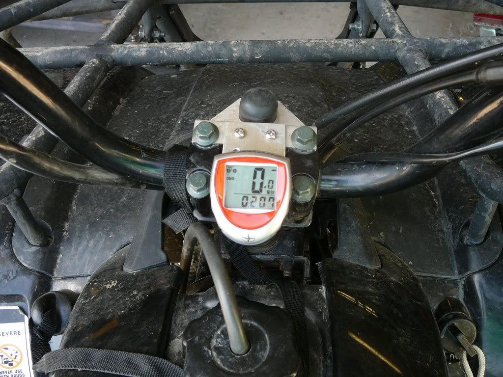 I mounted the display on a bracket I had already added a while back when I installed a horn. You can see the bracket and horn button below. 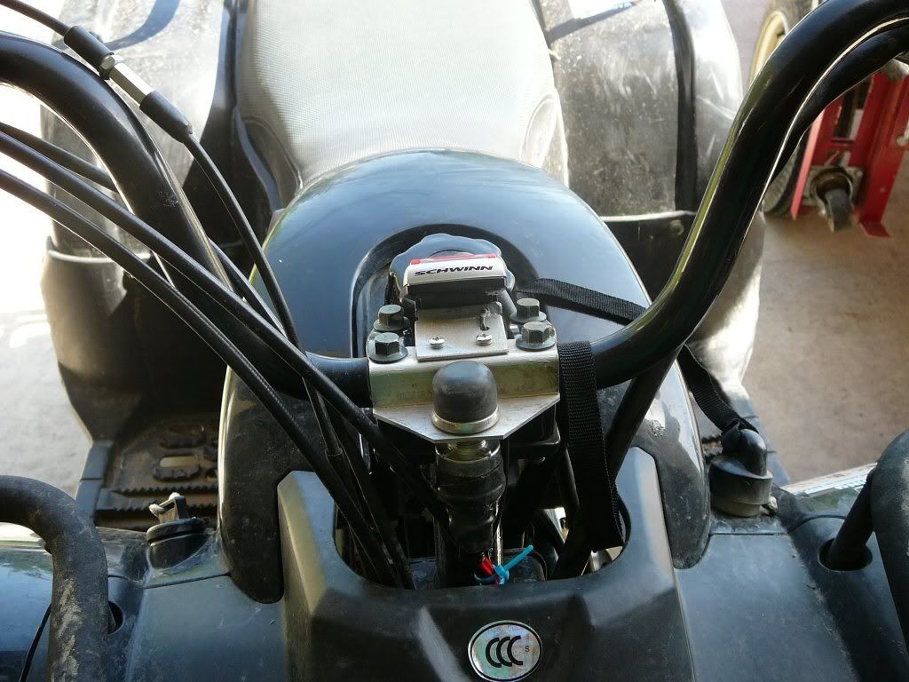 The following two pics show the pickup sensor and the magnet holder: 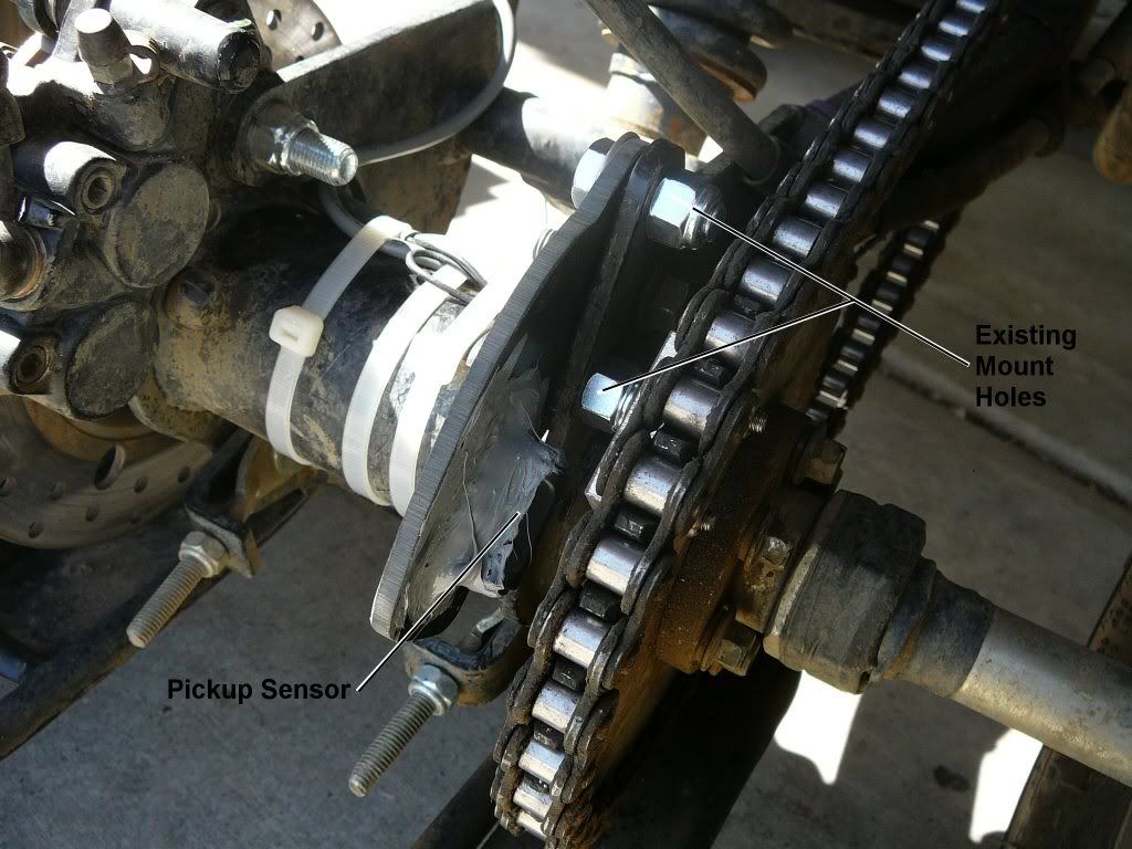 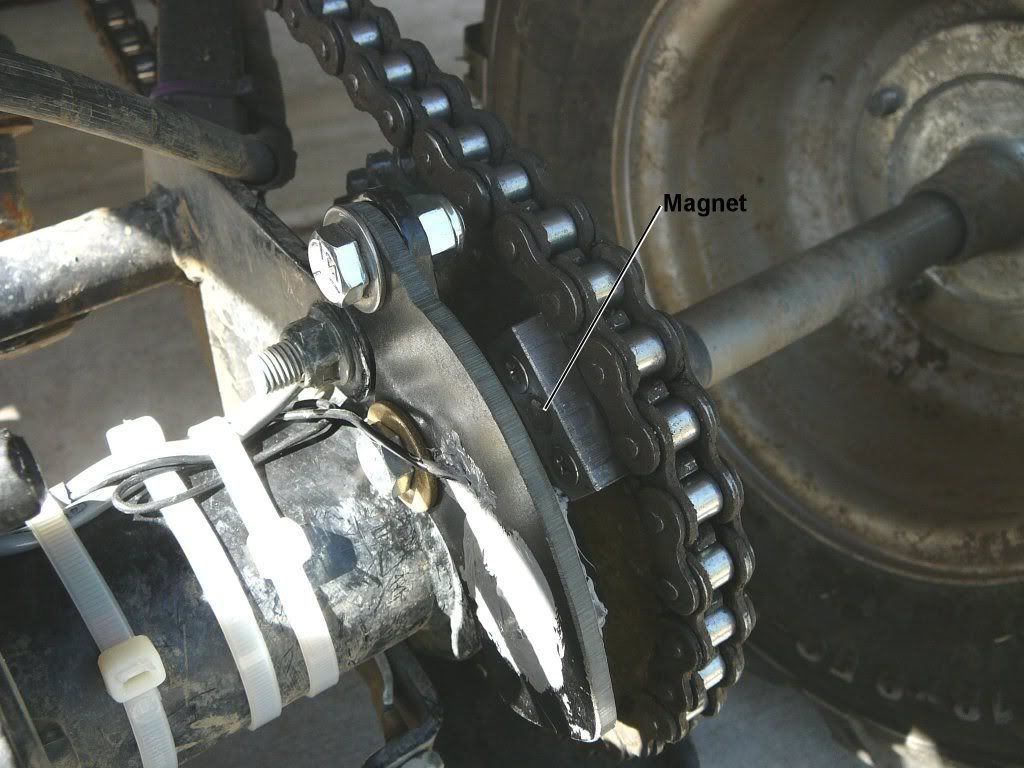 The magnet holder is made from a hunk of 3/8" scrap aluminum bar which is bolted to the axle drive sprocket with two 10x32 stainless screws and nylon insert locknuts. I epoxied a stack of three exotic high strength magnets in the center bore of the holder. Tests showed the pickup coil saw these magnets reliably out to more than 5/8", though it turns out the simplest mounting scheme for my quad put them much closer at around 3/8". I would have had to go out of my way to make that distance greater. It was not possible for me to use the brake rotor as Mobus did. I have a funny bulge near the center of the rotor that makes this impractical. The drive sprocket works fine. The steel isn't hardened and drills easy. If the chain comes off then my sensor is probably toast, but a new speedo is cheap. In the hundreds of hours on my quad I never had the chain come off yet. The pickup sensor is mounted on a plate made from a scrap hunk of 3/16" thick XX grade phenolic. Aluminum, fiberglass, or steel would work just as well. Note how I have the sensor mounted 90 degrees out from it's normal orientation on a bicycle installation. It doesn't seem to matter as far as I can tell. Rather than use the tie wraps provided I tied it down with multiple knots of lacing cord, then glued it in place with 3145 RTV silicone rubber. Epoxy would work too. I used two existing holes on the axle hub to mount the sensor plate. To design the sensor bracket to fit these holes I used Mobus' technique of using "cardstock" to model the needed bracket until it fit the complex contour of the axle hub and mounting holes. You start off with a piece of cardboard and whittle it down with a pair of scissors to make it fit. When you whittle too much just trace it to a new piece of cardboard adding more area as needed and start again. The picture below shows my cardstock template and a semifinished bracket. The other stuff is work in progress to make the second speedo. My next door neighbor has exactly the same qaud as I do and wants a speedo on his now too. 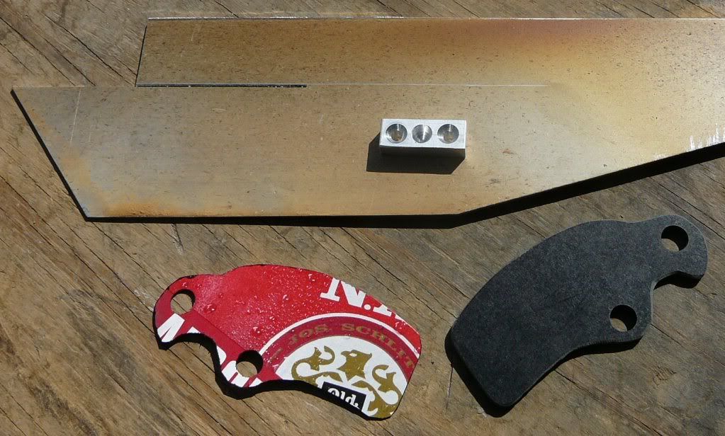 Next picture shows the wire routing up the swing arm. Note that the stock speedo cable is way too short. I cut it and added about 4 feet of cable to extend it to the handle bars. When connecting up the added cable, polarity doesn't matter. 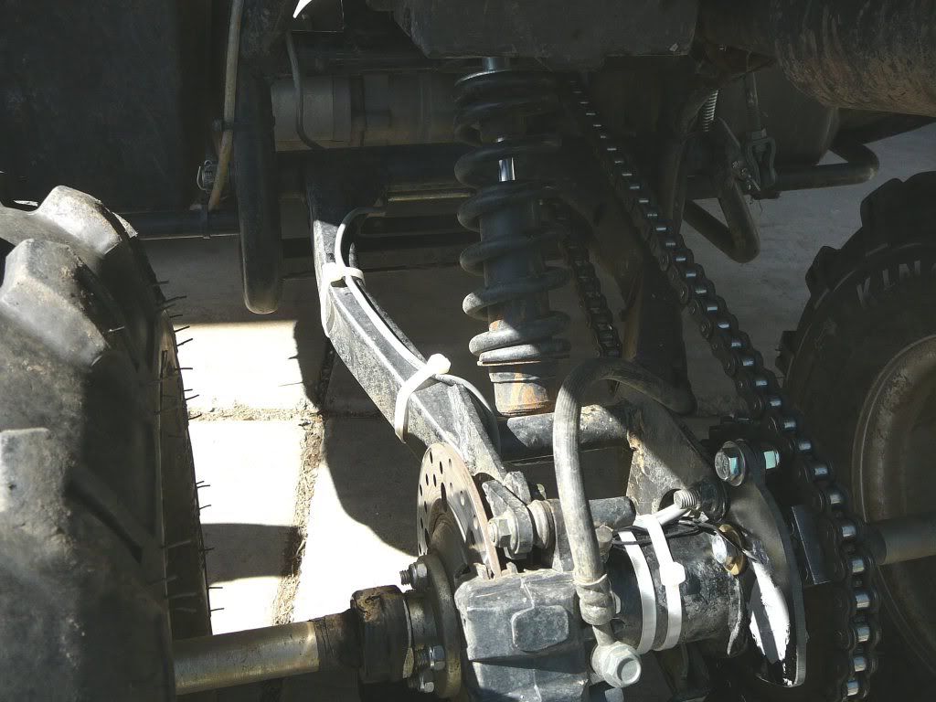 To measure and calibrate the speedo to my wheel circumference I compared two different methods: 1) I used a tape measure to measure the circimference directly. I got 4 feet 8 inches, or 56 inches, or 1422mm 2) I used Katoranger's paint the wheel and mark the concrete method and got 4 feet 7 1/4 inches, or 55.25 inches or 1403mm This is an error of about 1%. Either one is close enough for my requirements. If I'm going 30 miles per hour I don't much care if my speedo tells me it is 29.7 or 30.3 MPH. I've tried this on the street in front of my house. It will be at least four weeks before I can try this thing on real terrain. I have a new project which will keep me working at home on the weekends until then. If I find anything flakey I'll report back. All in all this was an easy install. Lynn Edwards Note: Edited to give proper credit to Mobus earlier posts. |
|
|
|
|

|
 |
|
|


 Linear Mode

